Home

Cocinando Instantáneamente diente buck boost converter dcm formula va a decidir Almuerzo Abolido

Currents and voltage waveforms of DCM buck–boost. | Download Scientific  Diagram
Currents and voltage waveforms of DCM buck–boost. | Download Scientific Diagram

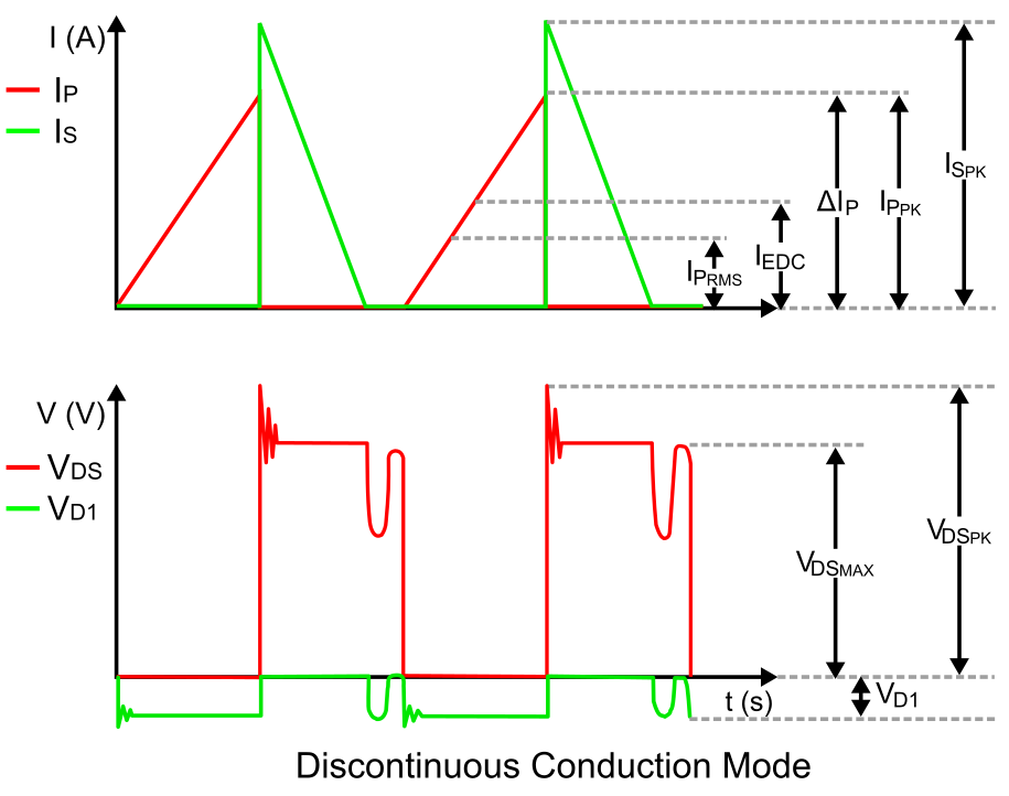
Power Tips #98: Designing a DCM flyback converter - EDN Asia

a) DCM/CCM detection circuit. (b) Idealized DCM/CCM detection... | Download  Scientific Diagram
a) DCM/CCM detection circuit. (b) Idealized DCM/CCM detection... | Download Scientific Diagram

How boost converter works? - Quora

Discontinuous Conduction Mode of Simple Converters - Technical Articles

Buck converter - Wikipedia

1 Sample converter topologies and operating modes: (a) Synchronous buck...  | Download Scientific Diagram
1 Sample converter topologies and operating modes: (a) Synchronous buck... | Download Scientific Diagram

Derivation of network functions for PWM DC-DC Buck converter in DCM  including effects of parasitic components on diode duty-cycle | Semantic  Scholar
Derivation of network functions for PWM DC-DC Buck converter in DCM including effects of parasitic components on diode duty-cycle | Semantic Scholar

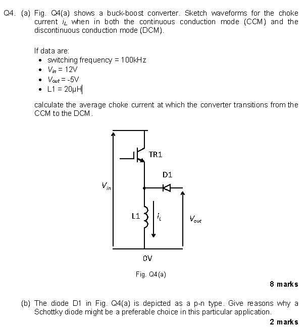
Solved Q4. (a) Fig. Q4(a) shows a buck-boost converter. | Chegg.com

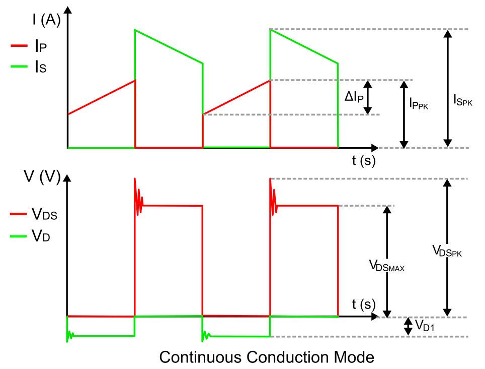
The Difference between CCM and DCM Explained | Article | MPS

Buck–boost converter - Wikipedia

Buck-boost Converter 3-3-1 Circuit diagram and key

Discontinuous Conduction Mode of Simple Converters - Technical Articles

a) Boost converter circuit diagram and (b) idealized state variable... |  Download Scientific Diagram
a) Boost converter circuit diagram and (b) idealized state variable... | Download Scientific Diagram

The Difference between CCM and DCM Explained | Article | MPS

Book excerpt: Switching Power Supply, Design and Optimization, CHAPTER 4,  Part 2 of 2 - EDN
Book excerpt: Switching Power Supply, Design and Optimization, CHAPTER 4, Part 2 of 2 - EDN

DC-DC converter DCM analysis - NXP Community

The DC-DC Boost Converter – Power Supply Design Tutorial Section 5-1 -  Power Electronics News
The DC-DC Boost Converter – Power Supply Design Tutorial Section 5-1 - Power Electronics News

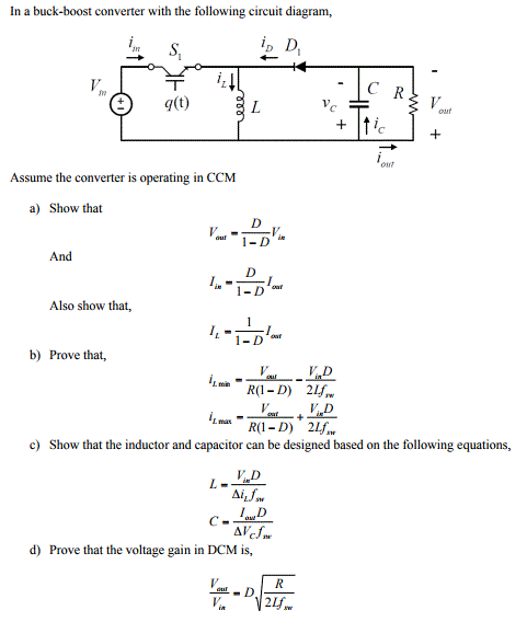
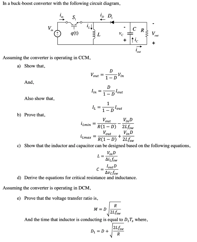
Solved In a buck-boost converter with the following circuit | Chegg.com

Solved In a buck-boost converter with the following circuit | Chegg.com

Buck–boost converter - Wikipedia

Buck-Boost Converter Analysis

Power Supply Design Tutorial (Part 1-2) - Topologies and Fundamentals,  continued - Power Electronics News
Power Supply Design Tutorial (Part 1-2) - Topologies and Fundamentals, continued - Power Electronics News

Buck converter under DCM (a) inductor current (b) capacitor current (c)...  | Download Scientific Diagram
Buck converter under DCM (a) inductor current (b) capacitor current (c)... | Download Scientific Diagram

DC-DC converter DCM analysis - NXP Community

Book excerpt: Switching Power Supply, Design and Optimization, CHAPTER 4,  Part 1 of 2 - EDN
Book excerpt: Switching Power Supply, Design and Optimization, CHAPTER 4, Part 1 of 2 - EDN

View of Power Loss Analysis Model of a Dc-Dc Buck-Boost Converter with an  Interfaced Three Phase Inverter for Medium Voltage Application | Journal of  Asian Scientific Research
View of Power Loss Analysis Model of a Dc-Dc Buck-Boost Converter with an Interfaced Three Phase Inverter for Medium Voltage Application | Journal of Asian Scientific Research
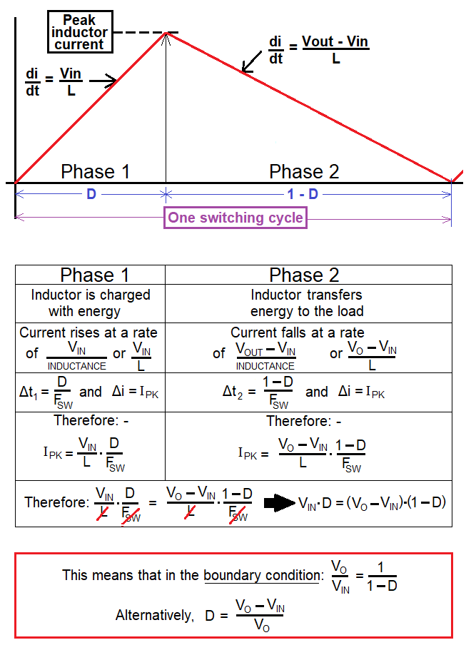
BOOST CALCULATOR The calculator's screen displays inductor current. The DCM  - CCM boundary is shown as dotted purple lines. DCM lines are red and  green. CCM lines are blue and orange. The UP UP and DOWN DOWN buttons  adjust the vertical ...
BOOST CALCULATOR The calculator's screen displays inductor current. The DCM - CCM boundary is shown as dotted purple lines. DCM lines are red and green. CCM lines are blue and orange. The UP UP and DOWN DOWN buttons adjust the vertical ...